- Red Hat Linux 7.3 has been installed on the server host with the non firewall option. That is, the no firewall option of the security level in the firewall configuration has been set at the installation time.
- The server host must have at least 500 Mbytes of disk space under the /opt directory.
- Compute hosts will be installed from scratch.
- You have an SCore CD-ROM or CD-ROM image.
- Configuration Specification using EIT
- Compute Hosts Installation
- SCore Server Configuration
The EIT version 4 requires temporal IP addresses which a DHCP server uses during the installation. However, the EIT version 5 does not require such temporal IP addresses because the EIT daemon is introduced to act as a DHCP server which gives a compute host IP address to the compute host during the installaion.
EIT generates an installation floppy disk image which does not include any compute host local settings. All installation images for compute host are located on the server.
EIT will invoke a daemon which handles the DHCP protocol, whose port number is 1641 instead of the standard DHCP server port number, 67. After booting an installer on a compute host by the boot floppy disk, the installer obtains its IP address from the daemon. The given IP address is permanently used in the compute host. Then, the compute host mounts installation images and invokes the Red Hat anaconda with a kickstart file stored in the server.
Be sure that you must login the server as a super user and the command path includes /sbin and /usr/sbin. That is, for example, make sure that the following command is successfully invoked:
# ifconfig eth0
	# mount /mnt/cdrom
	# cd /mnt/cdrom/
	# ./Install
You will find the /opt/score directory. The SCore Document and the EIT package have been installed under the directory.
- In case that the NIS server exists
- For example, assume that NISDOMAIN is score.info, issue the following command:
# /opt/score/bin/configNIS client score.info - Make sure that IP addresses of the server host and all compute hosts are registered in NIS.
- For example, assume that NISDOMAIN is score.info, issue the following command:
- In case that the NIS server is going to be set up on the SCore server.
- IP addresses of the server host and all compute hosts must be registered in the /etc/hosts file.
- Create user accounts.
- The configNIS command is used as follows to set up the NIS server.
In this example, the score.info NISDOMAIN name is assumed.
# /opt/score/bin/configNIS server score.info
- In case that NIS and DNS are running
# /opt/score/bin/eit
- In case that NIS is only running
# /opt/score/bin/eit -nisonly
![[Easy Installation Tool Welcome Window]](../../images/eit5-welcome.png)
Please click the Next button to start the installation.
- Keyboard Selection
You will see the keyboard selection window as shown below. Choose the keyboard type.![[Keyboard Selection]](../../images/eit5-keyboard.png)
Figure 2: Keyboard Selection Please click the Next button to configure the network information.
- Network Configuration
You will see the following window:![[Network Configuration]](../../images/eit5-network.png)
Figure 3: Network Configuration Basically, you do not need to modify the network configuration. If the SCore Cluster Development Kit CD-ROM image is stored in a hard disk, the "Mount Point" must be changed.- Server Name
You do not need to change it. - Domain Name
The domain name is the server host domain name. - Netmask
If your cluster host netmask is different from the default netmask, please modify this value. - Gateway
If the gateway of your compute host is different from the default gateway, please modify this value. - NIS
If the NIS domain name is different from the default name, please modify this value. - Mount Point
The directory of the SCore Cluster Development Kit CD-ROM image must be specified in this field. - Display
The display host to show the installation process should be specified.
- A dialog box will be displayed asking you to insert the SCore Cluster Development Kit CDROM into your CD drive if the specified mount point
is "/mnt/cdrom" and you have never mounted a CDROM(Figure 3):
![[Insert CDROM]](../../images/eit5-mount.png)
Figure 4: Insert CDROM - Insert the SCore CDROM and click the OK button.
Please click the Next button to configure the disk partition on compute hosts.
- Server Name
- Disk Partition
You will see the window shown in Figure 5:![[Disk Partition]](../../images/eit5-disk.png)
Figure 5: Disk Partition - Choose the size of the disk. Note that the file system partition sizes change automatically to pre-defined values for the size of disk.
- If necessary, enter values for in the boxes for custom file system sizes
- click the Next button to proceed.
- NFS Configuration
You may specify the NFS mount points in all compute hosts using the NFS Configuration section (Figure 6).![[NFS Configuration]](../../images/eit5-nfs.png)
Figure 6: NFS Configuration After specifying the NFS mount, please click the Next button. - Host Information
The next step is to specify the compute host information.![[Host Information]](../../images/eit5-host.png)
Figure 7: Host Information In the host information section (Figure 7),- Specify the number of compute hosts in the Number of Hosts field. For example, if your cluster will have one server and eight compute hosts, change this value to 8.
- Each compute host name will be a string specified in the Name Prefix filed followed by a number whose number system is selected from the buttons, digit, hex and oct. If you select none, then no number is added.
- The number is started from the value specified in the Start field.
- Figure of the number is specified in the Figure field.
For example, if you want to have four compute hosts with the postfix having the form 005, 006, 007, and 008, then enter 5 in the Start field and 3 in the Figure part. -
If compute hosts are SMPs, the number of processors is set in the # of Processors field.
- Click the Add button
- A Hosts Configuration dialog box will be displayed showing all
the hostnames that will be used, starting from 0 (Figure 8):
![[Hosts Configuration]](../../images/eit5-hostconf.png)
Figure 8: Hosts Configuration - Select OK to accept this list, or Cancel to start again
If you finish to specify all compute hosts, please click the Next button.
- Cluster Network Configuration
The Cluster Network Configuration section will be displayed (Figure 9).![[Cluster Network Configuration]](../../images/eit5-group-1.png)
Figure 9: Cluster Network Configuration (1) To specify the cluster group with network types, please click the New button. You will see the following window (Figure 10).![[Cluster Network Configuration]](../../images/eit5-group-2.png)
Figure 10: Group Creation (1) - Enter the name of the group in the text field at the top.
- Below the group name specification field, each network type has a toggle button. Select the networks that you wish to use by toggling the buttons. If you also select "Shmem" for SMPs enter the process count in the text field to the right. The process count should not be larger than the number of CPUs in the SMP machine.
-
On the left-hand side of the window is a box of candidate hosts. If the number of hosts cannot be displayed in the window you can scroll the window with the scroll bar. Select the hosts that you want for the group. The selected hosts will be displayed in the box on the right-hand side.
A button under the candidates and selected windows should be selected if you want to select all of machines, half of machines, or quarter machines. For example, if you want to select the first half of machines, click the 1/2 button. If you want to select the last half of machines, click the 2/2 button.
After entering the information you will see a window similar to the following (Figure 11).
![[Group Creation]](../../images/eit5-group-3.png)
Figure 11: Group Creation (2) - If you select Myrinet, Myrinet-2000 pr Myrinet XP, the Myrinet switch configuration window will appear after this window to create a Myrinet configuration file. You have to connect PCs for Myrinet according to the Myrinet Configuration page or Myrinet-2000 Configuration page.
- Click the OK button to accept this group, or Cancel to start again.
If you select the OK button, you will see the following window (Figure 12).
![[Group Creation]](../../images/eit5-group-4.png)
Figure 12: Cluster Network Configuration (2) To go to the next step, please click the Next button.
![[Myrinet Configuration]](../../images/eit5-myrinetconf.png)
Figure 13: Myrinet Network Configuration - Select Boot Network Device
Since a boot floppy disk cannot include all possible network device drivers, two devices, 100 Mbps and 1 Gbps Ethernet drivers, are separated in this release. If your comput hosts are connected to the server host by a 100 Mbps Ethernet, select the 100Mbps_Ethernet in the following window. If your comput hosts are connected to the server host by a 1 Gbps Ethernet, select the 1Gbps_Ethernet in the following window.Then, please click the Next button.
![[Select Boot Network Device]](../../images/eit5-selboot.png)
Figure 14: Select Boot Network Device - Create Boot Floppy
To create boot floppy disks, click the Create Boot Floppy button.![[Create Boot Floppy]](../../images/eit5-floppy-main.png)
Figure 15: Create Boot Floppy - A dialog box will be displayed asking you to insert a floppy disk into your floppy drive (Figure 16):
![[Insert Boot Floppy Disk]](../../images/eit5-floppy-insert.png)
Figure 16: Insert a floppy disk - Insert a blank floppy disk and select OK. The floppy disk must be initialized as the MSDOS format.
- After the floppy disk is written, a dialog box will be displayed asking you to remove the floppy disk.
- Remove the disk and select OK
- The system asks if you want to make a boot floppy disk more. The boot floppy disks are identical. Thus, you may reuse a boot floppy created in the server in another compute host installation.
- A dialog box will be displayed asking you to insert a floppy disk into your floppy drive (Figure 16):
- Cluster Setup
After the boot floppy creation section and the Cluster Setup section is displayed, it is ready to install all compute hosts.
![[Cluster Setup]](../../images/eit5-cluster-main.png)
Figure 17: Cluster Setup (1) - Insert a floppy disk into the compute host 0 and power on.
- Few minutes later, you will see the compute host 0 MAC address and
IP address in the Cluster Setup Window as shown in Figure 18.
![[Cluster Setup 2]](../../images/eit5-cluster-2.png)
Figure 18: Cluster Setup (2) At this time, the EIT daemon gives the IP address to the compute host. You may eject the boot floppy disk and insert it to the next compute host and power it on to start the installation.
After seeing the compute host information, the following window will be displayed. The window should be moved to some place because other installation windows will appear at the same location later.
When the confirmation window as shown in Figure 19 is displayed, please click the Next button in this window to install the cluster host.
![[Begin Installation]](../../images/eit5-anaconda-confirm.png)
Figure 19: Confirmation - The following window will be displayed during the installation sequence:
![[Installing Packages]\](../../images/eit5-anaconda-packages.png)
Figure 20: Installing Packages - When the installation has completed, you will see the following window.
Please click the "Exit" button. The compute host will be rebooted.
![[Congratulation Window]](../../images/eit5-anaconda-congra.png)
Figure 21: Congratulation Window
If all compute hosts have been installed, then proceed the next step.
- Server Setup
After installing all compute hosts,
click the Next button in the EIT window to set up the server host.
![[Server Setup]](../../images/eit5-server-main.png)
Figure 22: Server Setup The following message will appear when the server host set up is done.
![[Server Setup Done]](../../images/eit5-server-done.png)
Figure 23: Server Setup Done ![[Congratulation]](../../images/eit5-congra.png)
Figure 24: Congratulation ! Before testing the cluster, you have to logout and login again so that the shell environment variables, defined under the
/etc/profile.d, become effective.
If you want to configure that the Server host is also a compute host, the server host must be also included in compute host lists.
For example, let us add the server host to the compute hosts in the example configuration. That is, assume the eight compute hosts have been registered and the server host name isserver.pccluster.org.
Assume that you have not configured the SCore system, i.e., not yet proceeded the Cluster Network Configuration section. If you have configured compute hosts already, See the Additional Compute Hosts after Setting section.
-
In the host information section shown in Figure 25,
- Specify 1 in the Number of Hosts field,
- Fill the letter
serverin the Name Prefix field, - Select the none button
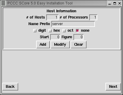
Figure 25: Host Information Then, you will see the following window. Click the OK button.
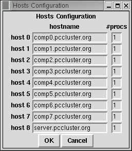
Figure 26: Hosts Configuration - Click the "New" button in the Cluster Network Configuration section and then specify the network.
If you will add more compute hosts in your cluster in the future, it is better that a server host is the compute host number 0 instead of the last number. If you want to set up this, the server host name is firstly registered in the host information section, and then other compute host names are registered.
If you want to add more compute hosts after configured, please do the following:
- Invoking
/opt/score/bin/eit - Click the Load button so that the configuration information is loaded.
- Specify the new additional compute hosts in the Host Information. A new compute host can be the server host. You may specify the server host name in the Host Information.
- Modify the existing network group or create a new network group in the Cluster Network Configuration section.
- Then click the Next button in the Cluster Network Configuration
section.
You will see the following dialog. Please click the No button
because existing compute hosts do not need to be reconfigured.
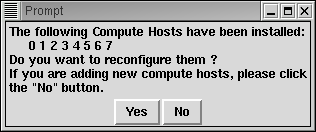
Figure 27: Reconfiguration Confirmation Click the No button !
- If you still keep boot floppies, use them to set up the new compute hosts. If you do not have them, create boot floppies in the Create Boot Floppy section.
- If the new compute hosts include the server host, the server host must be rebooted.
- During the linux kernel booting, the network cannot be initialized sometimes. In this case, you have to reboot it again.